
Meanderer trike toe and Ackerman fine-tuning
Here are the last few posts in the prototype-2 leaning full-suspension tadpole trike, called the "Meanderer":
- More tilting trike designs found — August 30, 2025
- Meanderer leaning trike video PART3 — August 25, 2025
- Meanderer trike steering and leaning design — August 24, 2025
I have been further simulating the steering and tilting linkages, trying to optimise it. Here is the latest 3D pictorial view:

The steering arms are now below the seat. The hand grips will probably be oriented sloping forward rather then out. Partly to reduce width of the trike, but also quite natural for the hands I think. The hand grips will be placed where the arms naturally fall down when the occupant is seated, and it should feel quite comfortable.
Another change is the mounting of the heim joints for the steering tie-rods has been moved to side-by-side, with centre-to-centre spacing of 80mm. This has been done obtain more accurate Ackerman compensation. This diagram shows how the wheels turn appropriately, inside wheel turning a bit more than the outside wheel:
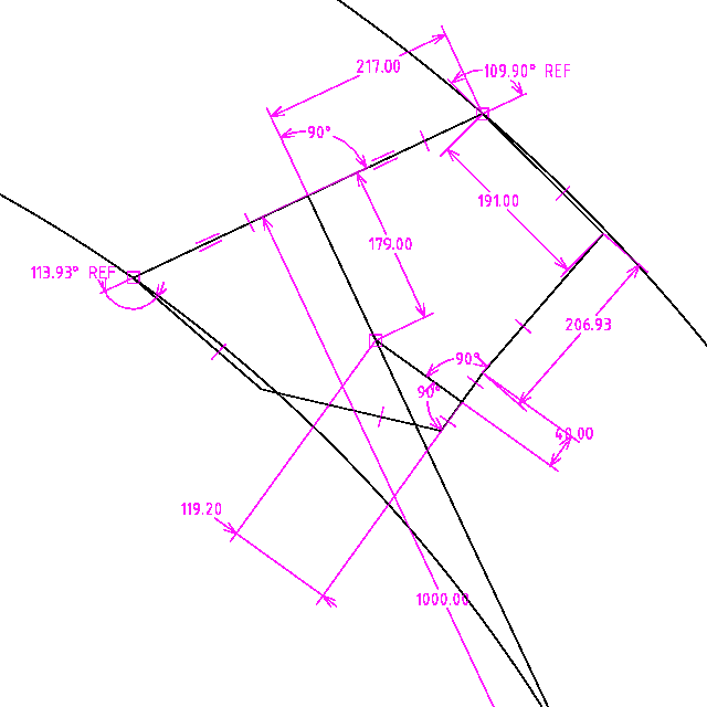
...what you should be able to see in that diagram, is that the inside wheel has not turned quite enough. Actually, I have read that this is sometimes desirable, not to have perfect Ackerman.
Anyway, I have deliberately made the Ackerman slightly off, due to the two inside heim joints. When cornering, it will be natural to tilt into the corner, and the heim joints will rotate like this, when turning left:

...what that will do is pull the left wheel a bit more than the right wheel, that is, will pull the left wheel closer to perfect Ackerman.
Simulating in 2 dimensions is very limited. Ideally I should
construct a complete 3D model. Anyway, making the closest guesses.
Toe-in is when the wheels are turned inward, rather than parallel. Interestingly, I have read that a tiny bit of toe-in may be a good thing.
The "toe" is likely to change a bit when turning, due to compromises in the linkages. It is also likely to change when a wheel hits a bump. If just a bump on one front wheel, the shock-absorber will compress as the wheel rises, and the wheel knuckle also rises, along with the end of the steering tie-rod connected to the knuckle steering-arm.
Here is the photo again of my trike #1 upside down:

...you can kind of get a picture of how complicated it is when one wheel deflects. It is likely that "toe" will change. If a tyre deflects in or out when going over a bump, that is going to result in increased rubber wear.
In prototype-2, I have been playing with offsetting the heim joint mounting vertically, such as this:

...looking horizontally at the suspension, the red line is the tie-rod. On the inside, the heim-joint is a little bit above the 12mm rod, and out by 40mm. On the other side, I have experimented with offsetting the heim-joint directly below the level of the wheel axle, in the above example, by 60mm. The idea is, that when the wheel hits a bump, the tie-rod will not change the toe, not by very much anyway.
There are so many variable. It is a matter of approximating such that performance is passable. Undoubtebly there will be some tyre scrubbing under certain situations. I need to build it best as can, then probably tweak things afterwards.Tags: light