Design of front suspension for recumbent tadpole trike
Continuing the custom solar recumbent trike project. The last
couple of posts:
- An easy-to-use pop rivet gun — October 11, 2023
- Solar recumbent trike solar panel design — October 08, 2023
The trike has coil suspension for the rear wheel, but no
suspension for the front wheels. I want to be able to ride the
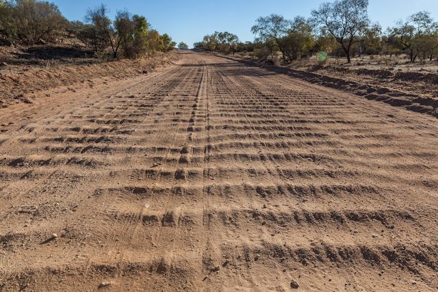
trike on very rough roads, even heavily corrugated gravel roads
like this:

...there are thousands of kilometres of roads like this in inland
Australia. Without front suspension, the trike would be destroyed.
Well, even if I ride very slowly, it will not be pleasant.
I bought a very cheap go-kart/buggy/ATV front suspension kit:

Will post more details about that, such as how it will be fitted
to the trike. For now, some preliminary designing...
This kind of suspension is known as "double-wishbone" or "double
A-arm". It is a complicated science to get a vehicle suspension to
work satisfactorily. This webpage explains "camber", "castor" and
"toe":
https://www.ozzytyres.com.au/news/wheel-alignment-101-lets-talk-camber-caster-toe
I think it is good to have slight negative camber on a tadpole
trike (top of wheel will be tilted inward). At least, that is my
understanding after a couple of days reading. Trikes have bicycle
tyres, with rounded tread, so they handle camber OK. Furthermore,
I think that it would be good if the camber becomes more negative
when the shock absorber is compressed.
Consider that corrugated road. Both front wheels will hit the
corrugation at the same time. The shock-absorbers will compress,
the wheels will move up, increasing the negative camber. But, at
the same time, the distance between the wheels in contact with the
road must remain the same.
If both wheels move up, and the distance between them on the road
surface increases, that will greatly increase tyre wear.
I used Solvespace and worked out proportions that satisfy both of
these requirements. Here is the Solvespace file, with a false
".gz" appended to the filename (that is, it isn't really
compressed):
Here it is exported to PNG:

...the circle is the central frame of the trike. The 200x200
square is a frame that I plan to manufacture, that will attach to
the tube frame. The rectangle is the wishbone-suspension.
Immediately to the right is a 90mm line which represents the
spindle for the wheel. The 250mm line at 90 degrees to the spindle
represents a 20" wheel.
I played with the coordinates and got it to work quite well. That
319.67 distance which is wheel contact on the road, remains within
about 2mm over the full range of the suspension. Maybe could tweak
it slightly more.
Another design consideration is cornering. The rider will be able
to lean into corners, and the wheels will also lean. This greatly
aids stability. I have designed it to have overall width of just
under 730mm, so as to be able to fit the trike through my front
door. Consequently, it is narrower than most trikes, that are over
800mm.
Being narrower, there is more risk of tipping when going round
corners. Except, this design allows the rider to lean into the
corner. Here is a Solvespace drawing showing leaning to the right:
suspension2e-lean-right2.slvs.gz

And leaning left:
suspension2e-lean-left2.slvs.gz

Look at the first diagram, it shows a distance from centre to
wheel of 319.67mm. Multiply by two gives 639.34mm.
Now look at the last two diagrams. 322.83 plus 316.78 gives
639.61mm. Good!
This means that the rider can tilt into a corner, and the wheels
will also tilt, while keeping the separation between wheels on the
road surface the same.
Looking good. One parameter that I do not know how to handle is
caster. It is neutral caster. I will rely on a dampener to reduce
any tendency of the wheels to wander from side to side. Not going
to ride any faster than 25km/hr anyway.
Toe will be handled using mechanisms already provided with the
trike.
Tags: light
